
The Xn interface is the inter-node communication link in 5G Standalone (SA) networks. It directly connects Next Generation NodeBs (gNBs) to each other, as well as Next Generation eNodeBs (ng-eNBs) to gNBs within the Next Generation Radio Access Network (NG-RAN).
Its main purpose is to handle user mobility, pass control signals, manage data forwarding, and coordinate radio resources without constantly bothering the 5G Core Network (5GC). By letting neighboring base stations talk to each other directly, the Xn interface drastically reduces handover delays and keeps active sessions smooth.
- Understanding the Xn Interface in 5G Networks (NG-RAN)
- Architectural Foundations & Protocol Stack Deep-Dive (Xn-C vs. Xn-U)
- Architectural Evolution: 4G X2 Interface vs. 5G Xn Interface
- Automatic Neighbor Relation (ANR) & Xn Interface Setup Workflow
- Mobility Management & End-to-End Xn Handover Call Flow
- RRC_INACTIVE State Management & RAN Paging Mechanism
- Dual Connectivity (NR-DC) & Secondary Node Management
- User Plane Flow Control & Quality of Service (QoS) Handling
- Protocol Testing, Log Analysis & Troubleshooting Scenarios
- Frequently Asked Questions (FAQs)
Understanding the Xn Interface in 5G Networks (NG-RAN)
In the Next Generation Radio Access Network (NG-RAN), base stations must communicate continuously to handle user mobility. The Xn interface provides a logical point-to-point connection between two gNBs, or between a gNB and an ng-eNB (an LTE base station connected to the 5G Core).
While 4G networks relied on the X2 interface, 5G Standalone (SA) mode requires the Xn interface to support advanced 5G capabilities. Its core function is to handle radio resource coordination, seamless active-mode handovers, and efficient user plane data forwarding across neighboring cells.
By handling local coordination directly between base stations, the Xn interface offloads repetitive signaling tasks from core network functions like the Access and Mobility Management Function (AMF) and User Plane Function (UPF).
Architectural Foundations & Protocol Stack Deep-Dive (Xn-C vs. Xn-U)
The Xn interface is split into two logical paths: the Control Plane (Xn-C) and the User Plane (Xn-U). Separation of control and user functions ensures that control messages remain prioritized, even during heavy user traffic.
Control Plane (Xn-C) Protocol Stack
The Xn Control Plane handles signaling between nodes. Its protocol stack follows a simple hierarchy:
- Application Layer: Xn Application Protocol (XnAP)
- Transport Layer: Stream Control Transmission Protocol (SCTP)
- Network Layer: Internet Protocol (IPv4/IPv6)
SCTP is vital here. Unlike standard TCP, SCTP offers multi-homing support and multi-streaming. Multi-homing allows a gNB to maintain backup network paths across multiple IP addresses. If one physical network path fails, SCTP keeps the XnAP signaling session alive, preventing dropped handovers.
User Plane (Xn-U) Protocol Stack
The Xn User Plane handles payload data transfer during active handovers. Its protocol stack includes:
- Application Protocol: NR User Plane Protocol
- Encapsulation Layer: GPRS Tunnelling Protocol User Plane (GTP-U)
- Transport Layer: User Datagram Protocol (UDP)
- Network Layer: Internet Protocol (IPv4/IPv6)
Data transport uses GTP-U tunnels identified by Tunnel Endpoint Identifiers (TEIDs). When a user moves between cells, the serving gNB encapsulates the user’s data packets inside GTP-U headers and routes them straight to the target gNB over UDP/IP.
3GPP Specification Reference Matrix
The design and behavior of the Xn interface are strictly governed by standard 3GPP specifications:
| 3GPP Specification | Scope and Description |
| TS 38.420 | Xn general aspects and main principles |
| TS 38.421 | Xn Layer 1 specifications |
| TS 38.422 | Xn signaling transport definitions |
| TS 38.423 | Xn Application Protocol (XnAP) specification |
| TS 38.424 | Xn data transport standards |
| TS 38.425 | Xn user plane protocol frame formats |
Architectural Evolution: 4G X2 Interface vs. 5G Xn Interface
While 5G Xn builds on 4G X2 concepts, several structural changes accommodate modern cloud-native architectures and strict Quality of Service (QoS) requirements.
Key Structural & Operational Differences
The 4G X2 interface was designed to connect legacy eNodeBs based on EPS Bearers. In contrast, 5G Xn operates natively on a fine-grained QoS Flow framework.
Xn natively supports 5G Network Slicing. It allows nodes to preserve slice isolation during node-to-node handovers. Xn also manages the RRC_INACTIVE state, a feature entirely absent in 4G X2.
X2 vs. Xn Interface Feature Comparison Matrix
| Feature | 4G X2 Interface | 5G Xn Interface |
| Connected Endpoints | eNB to eNB, or eNB to en-gNB | gNB to gNB, or ng-eNB to gNB |
| Core Network Anchor | Evolved Packet Core (EPC) | 5G Core Network (5GC) |
| QoS Management Model | EPS Bearer-based | QoS Flow-based |
| Radio States Supported | RRC Idle, RRC Connected | RRC Idle, RRC Connected, RRC Inactive |
| Dual Connectivity Modes | EN-DC (E-UTRA-NR) | NR-DC, NE-DC, NGEN-DC |
| Network Slicing Support | Not Supported | Native Support (NSSAI aware) |
Automatic Neighbor Relation (ANR) & Xn Interface Setup Workflow
Before two base stations can talk over Xn, they must discover each other and set up a transport connection.
Neighbor Identification via PCI and CGI Decoding
When a User Equipment (UE) moves near an unknown cell, it reports the target cell’s Physical Cell Identity (PCI) to its serving gNB. If the serving gNB does not have this PCI in its Neighbor Relation Table (NRT), it instructs the UE to read the target cell’s System Information Block 1 (SIB1).
The UE decodes the full Cell Global Identity (CGI), Tracking Area Code (TAC), and PLMN ID, then reports them back. The serving gNB uses this CGI to query the Access and Mobility Management Function (AMF) to obtain the target gNB’s transport IP address.
SCTP Association & Xn Setup Request/Response Handshake
Once the target IP is known, an SCTP connection is initialized on port 38422.
| Step | Source gNB Action | Direction | Target gNB Action | Description |
| 1 | Send SCTP INIT | Receive SCTP INIT | Initiates transport association | |
| 2 | Receive SCTP INIT ACK | Send SCTP INIT ACK | Acknowledges transport setup | |
| 3 | Send SCTP COOKIE ECHO | Receive SCTP COOKIE ECHO | Completes multi-homing cookie handshake | |
| 4 | Receive SCTP COOKIE ACK | Send SCTP COOKIE ACK | Confirms active SCTP channel | |
| 5 | Send XN SETUP REQUEST | Process configuration | Exchanges served cell capabilities & TACs | |
| 6 | Receive XN SETUP RESPONSE | Send XN SETUP RESPONSE | Finalizes application-level setup |
The originating node sends an XN SETUP REQUEST containing its operational metadata, supported TACs, and served cell capabilities. The receiving node verifies the information and responds with an XN SETUP RESPONSE. The Xn link is now ready for active traffic.
Mobility Management & End-to-End Xn Handover Call Flow
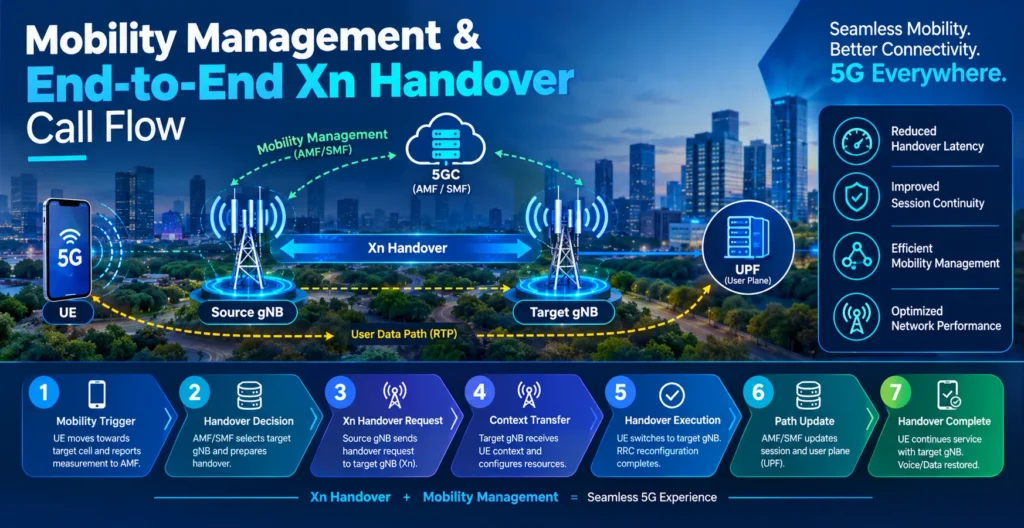
Handover keeps user calls and data sessions active as people move between coverage areas.
Preparation Phase & Target Resource Reservation
The serving gNB evaluates signal reports from the UE. If a neighbor cell shows better signal quality, the serving gNB sends an Xn Handover Request message over XnAP to the target gNB.
This message includes security context, target cell IDs, and required QoS flows. The target gNB runs admission control. If resources are available, it reserves a Cell Radio Network Temporary Identifier (C-RNTI), prepares downlink/uplink GTP-U TEIDs, and returns an Xn Handover Request Acknowledge containing the transparent RRC Reconfiguration container.
Execution & Lossless Data Forwarding over Xn-U
The serving gNB forwards the RRC Reconfiguration message to the UE, telling it to attach to the new cell.
To prevent packet loss during the transition, the serving gNB sends an SN Status Transfer message over Xn-C. This message specifies the last acknowledged Packet Data Convergence Protocol Sequence Number (PDCP SN). Simultaneously, in-flight downlink packets are encapsulated in GTP-U and forwarded over the Xn-U data tunnel to the target gNB’s buffer.
Completion Phase & UE Context Release
Once the UE successfully syncs with the target gNB, it returns an RRC Reconfiguration Complete message.
The target gNB sends an NGAP Path Switch Request to the AMF so the User Plane Function (UPF) switches the user data path toward the new gNB. After receiving the path switch acknowledgment, the target gNB sends an Xn UE Context Release message to the old gNB, clearing out the old buffer resources.
RRC_INACTIVE State Management & RAN Paging Mechanism
5G introduced the RRC_INACTIVE state to save device battery power while keeping connection setups nearly instantaneous.
RRC Inactive to RRC Connected Transitions
In this state, the UE drops its radio connection, but both the gNB (acting as an anchor) and the 5GC retain the UE’s full operational context.
When the UE moves to a new cell and needs to transmit data, it sends an RRC Resume Request. If the new cell is on a different gNB, the new gNB uses the Retrieve UE Context Request message over XnAP to fetch the stored security and bearer parameters directly from the anchor gNB.
RAN Notification Area (RNA) Paging over Xn
If downlink data arrives at the anchor gNB for an inactive UE, the core network does not page the device. Instead, the anchor gNB manages the process.
It distributes Xn RAN Paging signaling messages across all neighboring gNBs listed within the UE’s assigned RAN Notification Area (RNA) over the Xn interface. These gNBs then page the UE over their local air interfaces simultaneously.
Dual Connectivity (NR-DC) & Secondary Node Management
NR-Dual Connectivity (NR-DC) allows a UE to consume radio resources from two distinct base stations at the same time: a Master Node (MN) and a Secondary Node (SN).
Secondary Node Addition & Reconfiguration
The Master Node uses measurement reports to decide if adding secondary capacity will boost user throughput.
| Step | Initiating Node | Signaling Message | Direction | Receiving Node | Purpose |
| 1 | Master Node (MN) | S-gNB Addition Request | → | Secondary Node (SN) | Requests resource allocation for QoS flows |
| 2 | Secondary Node (SN) | S-gNB Addition Request Ack | ← | Master Node (MN) | Confirms radio resources & allocated TEIDs |
| 3 | Master Node / UE | RRC Reconfiguration | ←→ | User Equipment (UE) | Synchronizes UE air interface with Secondary Node |
| 4 | Master Node (MN) | S-gNB Reconfiguration Complete | → | Secondary Node (SN) | Confirms active secondary connectivity setup |
The MN sends an S-gNB Addition Request over XnAP requesting resource allocations for specific QoS flows. The SN evaluates its current hardware load and responds with an S-gNB Addition Request Acknowledge. Once the UE syncs with the secondary node, the MN confirms the setup by sending an S-gNB Reconfiguration Complete message.
Secondary Node Modification, Release, and Counter-Check
As radio conditions fluctuate, the MN or SN can initiate secondary node modifications to adjust allocated bearers or drop the link entirely using S-gNB Release Request messages.
To prevent security desynchronization on high-speed dual connections, nodes use the S-gNB Counter Check procedure over Xn. This message exchanges current PDCP COUNT values between nodes to detect ciphering desync or dropped frame counters before data corruption occurs.
User Plane Flow Control & Quality of Service (QoS) Handling
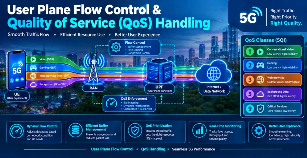
High-throughput 5G radio connections require active buffer monitoring across node boundaries.
Downlink Data Delivery Status (DDDS) Frame Formats
The NR User Plane protocol uses standardized frame formats across Xn-U to manage buffer overflow:
- Type 0 Frames: Carry sequence numbers and user data payloads.
- Type 1 Frames: Carry Downlink Data Delivery Status (DDDS) feedback reports without user payloads.
Type 1 DDDS frames are sent back from the target or secondary node to the anchor node. They carry critical details like the highest successfully delivered PDCP sequence number, lost packet notifications, and the target node’s desired buffer size in bytes.
QoS Flow Mapping & Guaranteed Bit Rate (GBR) Enforcement
If a cell experiences sudden radio interference, it might struggle to maintain Guaranteed Flow Bit Rate (GFBR) targets for live video or voice calls.
When this happens, the affected gNB issues a Notification Control Indication across the Xn interface. This triggers the serving anchor to adjust its scheduling, lower bitrates gracefully, or execute a targeted handover before the call drops.
Protocol Testing, Log Analysis & Troubleshooting Scenarios
Field engineers frequently analyze Xn interface traces using Wireshark or dedicated RAN analyzers to debug network performance issues.
SCTP Connection Failures & Firewall Diagnostics
- Symptom: Xn links fail to establish; base stations show Xn Setup Failure or transport link down alarms.
- Root Cause: Network firewalls blocking target ports, or misconfigured IP multi-homing paths.
- Troubleshooting Tip: Verify that UDP/IP ports for GTP-U (port 2152) and SCTP (port 38422) are open across middleboxes. Check Wireshark traces for missing SCTP INIT ACK responses. Ensure both primary and secondary IP addresses in the SCTP handshake match the configured transport parameter tables.
ANR Discovery Mismatches & Energy-Saving Cell Deactivation
- Symptom: Handover attempts fail consistently toward specific target cells during off-peak hours.
- Root Cause: The target cell was temporarily deactivated by central Energy Saving (ES) routines, but the source gNB’s Automatic Neighbor Relation (ANR) table failed to process the status update.
- Troubleshooting Tip: Check for missing NG-RAN Node Configuration Update messages over Xn. Confirm that base stations are set up to send configuration updates immediately whenever local cells are activated or deactivated for power-saving reasons.
Handover Failures & Missing Xn-U TEIDs
- Symptom: High rate of handover drops during the execution phase, accompanied by user plane data stalls.
- Root Cause: GTP-U Tunnel Endpoint Identifier (TEID) mismatches, or missing data forwarding configurations.
- Troubleshooting Tip: Inspect Xn Handover Request Acknowledge logs. Confirm that the target node returns valid, non-zero GTP-TEID values for the data forwarding tunnels. If user plane packets drop while control signals pass, check for mismatched VLAN tagging on the Xn-U transport link.
Frequently Asked Questions (FAQs)
What is the Xn handover call flow in 5G?
The 5G Xn handover call flow consists of three distinct phases:
- Preparation Phase: The source gNB sends an Xn Handover Request to the target gNB, which runs admission control and reserves local resources.
- Execution Phase: The source gNB instructs the UE to switch cells via an RRC Reconfiguration message, sends an SN Status Transfer message, and forwards buffered data over Xn-U GTP-U tunnels.
- Completion Phase: The target gNB verifies the UE attach, requests an NGAP Path Switch from the 5G Core, and sends an Xn UE Context Release message to clear out the source gNB’s old buffers.
What are the different types of 5G network interfaces?
The main 3GPP 5G network interfaces include:
- Xn Interface: Connects gNB to gNB or ng-eNB to gNB within the radio network.
- NG Interface: Connects the gNB to the 5G Core Network (split into NG-C / N2 for control signaling and NG-U / N3 for user data).
- F1 Interface: Connects the gNB Central Unit (gNB-CU) to the gNB Distributed Unit (gNB-DU).
- E1 Interface: Connects the gNB-CU Control Plane to the gNB-CU User Plane.
- Uu Interface: The radio interface connecting the User Equipment (UE) to the gNB.
Which is better, SA or NSA in 5G?
5G Standalone (SA) is better for long-term performance because it uses a native 5G Core Network alongside 5G base stations. This enables ultra-low latency, network slicing, massive IoT scale, and native direct Xn interface signaling. Non-Standalone (NSA) depends on an existing 4G EPC core and LTE anchor cells. While NSA allowed carriers to deploy 5G faster, it lacks modern 5G features like microsecond latency and deep network slicing.
What is the N8 interface used for in 5G?
The N8 interface connects the Unified Data Management (UDM) to the Access and Mobility Management Function (AMF) within the 5G Core Network. It lets the AMF fetch subscriber profile data, authentication credentials, and mobility management permissions when a user registers on the network.
What are the different types of handover in 5G?
5G networks support four main handover types:
- Intra-gNB Handover: Handover between different beams or sectors managed by the exact same gNB.
- Inter-gNB Xn Handover: Direct handover between two gNBs using the Xn interface without involving core network control signaling.
- Inter-gNB N2/NG Handover: Handover routed through the 5G Core Network when no direct Xn interface exists between the base stations.
- Inter-RAT Handover: Handover between different Radio Access Technologies, such as moving an active connection from 5G NR to 4G LTE.